Plasma Fusion in-vessel Antennas
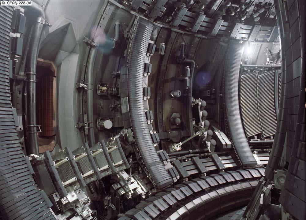
The inside of the JET vessel - the antenna is a small object ad middle height and 35 % across from the left
- Photo kindly provided by John Fessey Copyright Protected by UKAEA, Culham Science Centre and/or EFDA JET.
Recent information - April 08 - is that the antenna continues to perform well
Thomas Keating has long been associated with Plasma Fusion Diagnostics, but until 2003 had not been involved with any large in-vessel /plasma wall crossing components. In the Autumn of 2003 we won a competitive tender (only later did we discover that we were the only bidder!) to design and build a 6 channel plasma wall-crossing antenna feed for JET(technically now the European Fusion Development Organisation; EFDA). Two channels route oblique Electron Cyclotron Emission radiation to a diagnostic system. This will allow electron density measurements at a small angle to the magnetic field, allowing a search to be made for non-Maxwellian electron distribution. The remaining four are for Reflectometry, in the frequency range 60 - 200 GHz .
Working from the plasma end, in simple terms, radiation arrives at one of six long waveguide (possibly via a Quasi-optical mirror system detailed in the figures below) and passed down the waveguide (corrugated for the Reflectometry measurements). At the other end of this long structure – called the Window Box - it expands at the end of the waveguide and is refocused by two mirrors forming a QO zero-gain telescope, while passing through a double quartz window. The beam then enters a long corrugated guide to the diagnostics hall.
The project was quite an experience for TK – not only were there significant design and machining challanges, but the intensity of QA was at a higher level then we are used to, even for our Space projects: As our Antenna spans the vessel wall it must act a barrier to stop tritium leaking from the Torus – hence the double quartz window. Strict limits were placed on the choice of materials – basically the construction had to be made Stainless Steel, Aluminium Bronze and Macor (we could have use Inconel 600, but that is serviously bad news to machine). We learned alot about use use of machining fluids, cleaning process, the polishing of vacuum surfaces and how to test high vacuum components.
For more details of the ECE measurements see C.Sossi el al
How was it designed?
Using the Wildfire version of Pro/Engineer. Below you will see a series of images showing the power of Pro/E, generated by TK designer, Stuart Froud.
A rotatable “Edrawing” is available for download.
The geometry of the structure is more complex: Although the set of corrugated guide look straight, they are actually all incline at small angles – the cluster at the plasm end is smaller that at the Window Box end. In addition, the Guides leaving for the diagnostics hall are all inclined at an 8 degree angle. This lead to some interesting three dimensional geometry – a task which would have been nearly inpossible without Pro/E.
Given TK's knowedge and ability to machine accuractly and the level of QA require for welding (Full inspection, production of Production Proof Samples etc), a significant design aim was to minimise the number of welds: Only two areas were welded – the six windows, supplied by UKAEA Special Techniques, to the Top Hat structure and the long waveuide tube. Full vacuum testing was applied to the former – the latter was not at a vacuum wall.
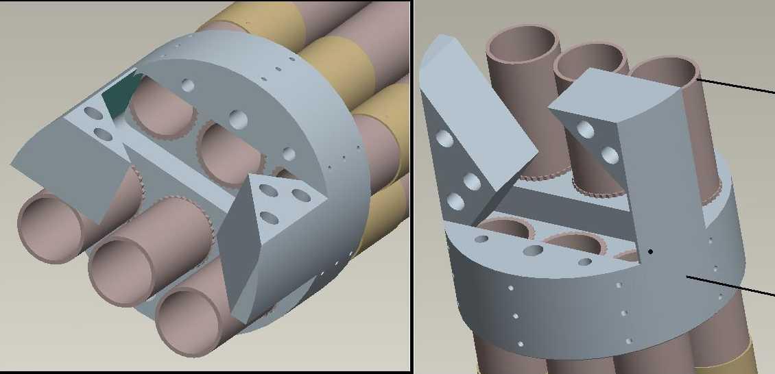
Drawings of the ECE offset mirrors at the plasma end:
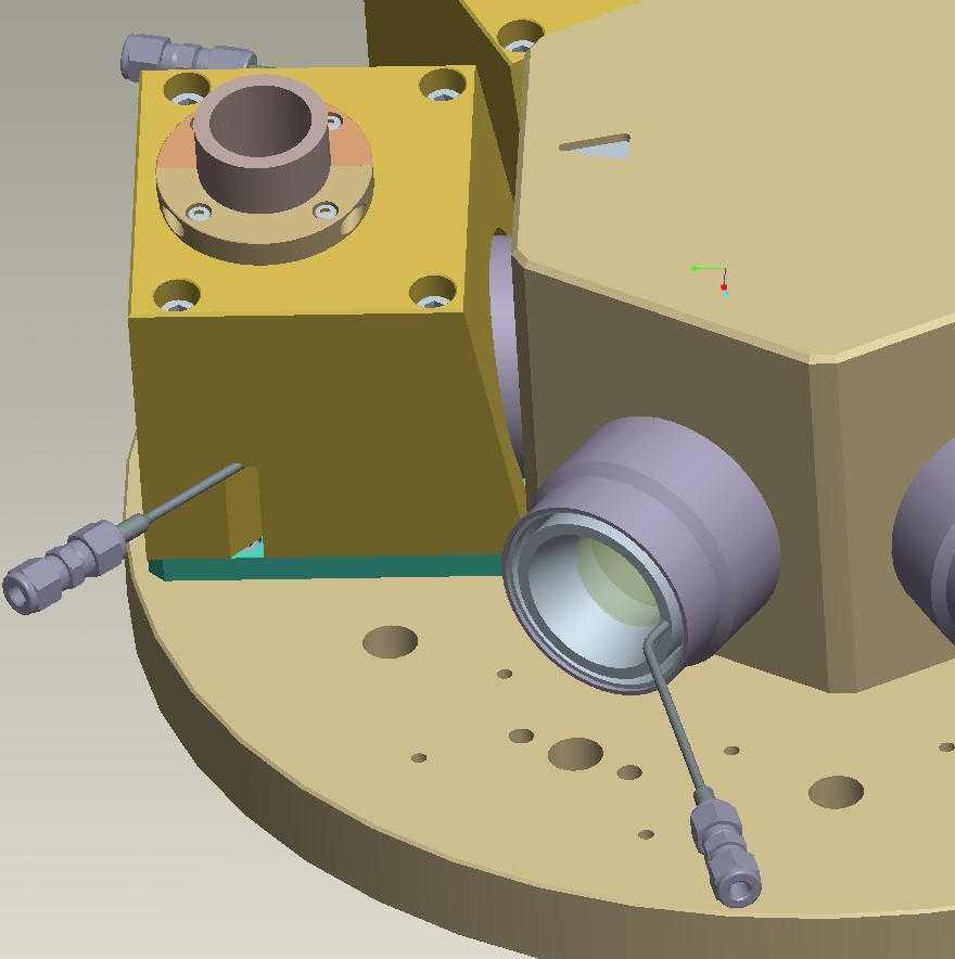
Here is a section of the window box end, showing both a completed mirror housing structure as well as an exposed window. Note the pumping port used to fill the interspace between the quartz windows. In operation, Neon gas is placed in the space at half an atmosphere pressure – mass spectrometers operating both inside and outside the vessel search for Ne, which would indicate a leak. By having two windows, the integrity of the vessel is enhanced – both would have to fail for Tritium to leak to atmosphere.
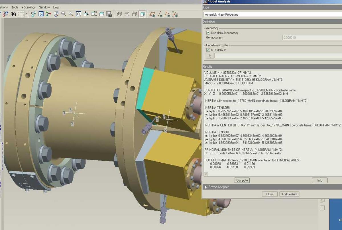
Here mass and moment-of-inertia properties are determined. There are potentially significant mechanical forces acting on the Antenna – particularly during a disruption (when the plasma fails). During such a disruption there will be large torques on the corrugated guides, coming from an interaction between the magnetic field and eddy currents associated with the collapse. The guide are anchored at both ends by splines to counteract such torques.
Manufacture
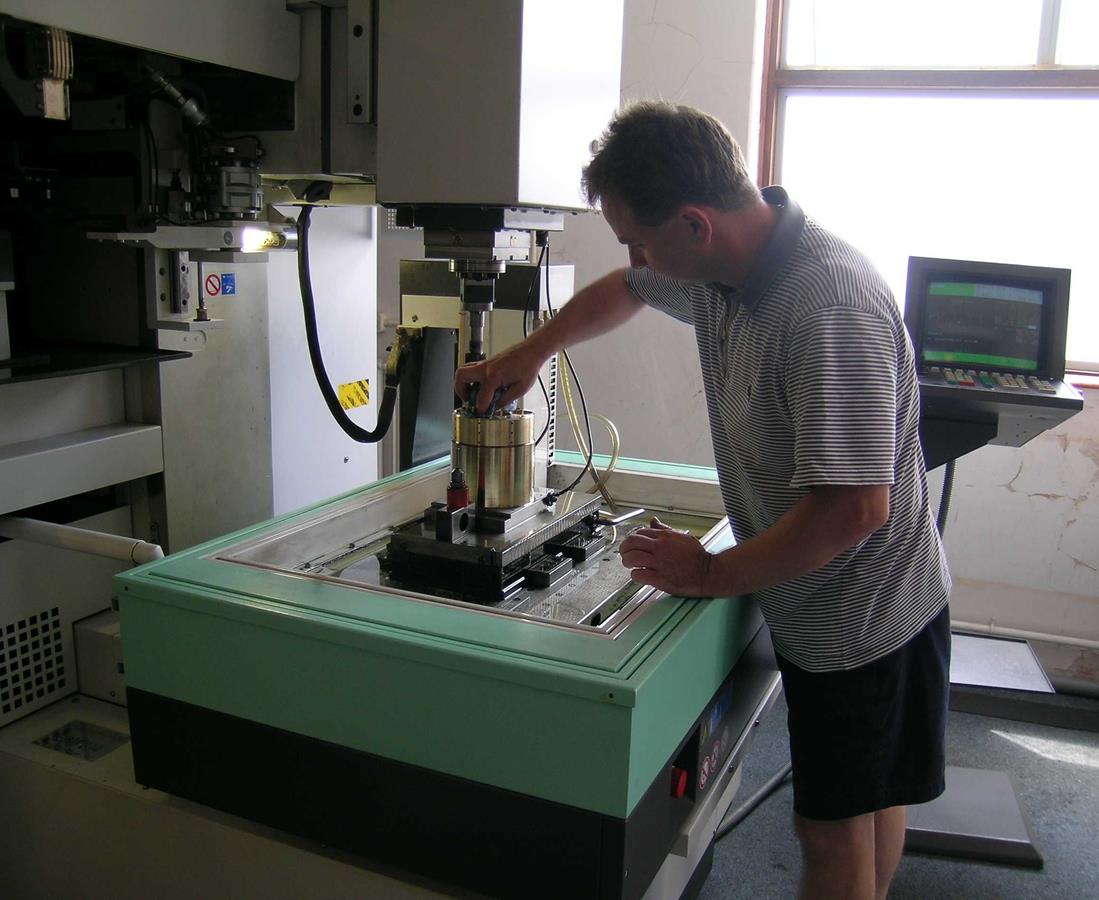
How as it made? Extensive use was made of direct CAD/CAM transfer of data: Foe example, the twelve mirror surfaces were directly machined by data passed from Pro/E via EdgeCAM using Pathtrace's Graphite software engine.
Here TK's Andy Bagley sets a CNC spark erosion to cut splines in the front antenna
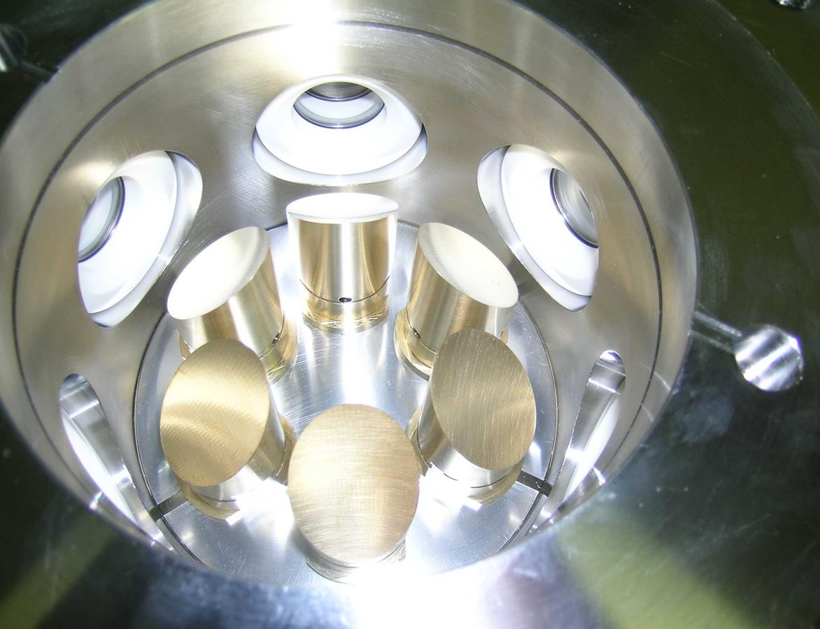
This picture shows the internal mirrors mounted inside the top hat section
Clean room assembly – here Trevor Walker inserts the mirrors into a Top Hat section. Macor inserts surround these and also the external mirrors to absorb, to some extent, any stray radiation.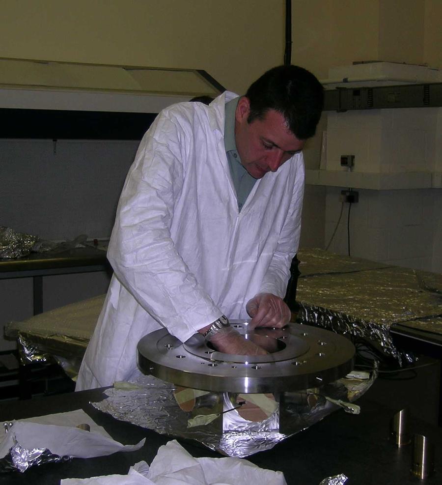
This shows the diagnostic ("Top Hat") end of the Antenna – with the Macor absorber ahead of the external mirrors being quite visable.
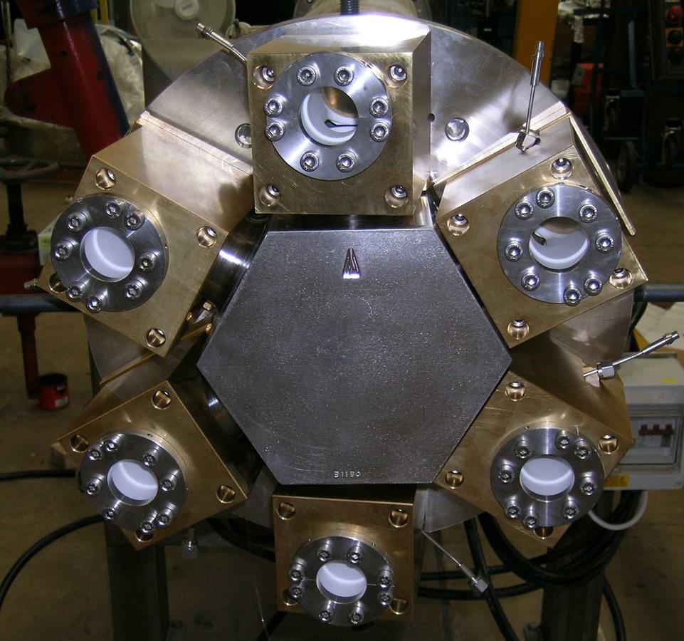
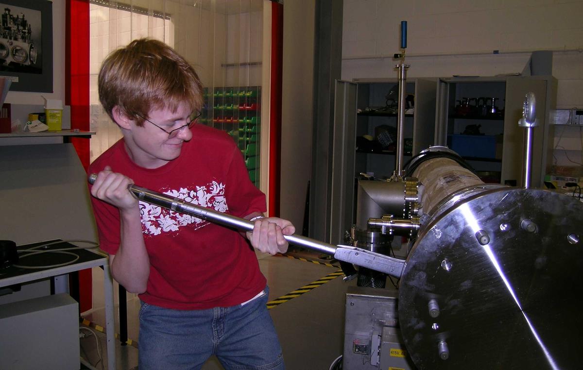
Also sorts of people help – including George Wylde, here seen tightening a vacuum flange during the test programme at Oxford-Danfysik in Oxford. ODf allow us to use their cleaning and clean room facilities and provided the vacuum diagnostic equiment to prove vacuum integrity at the 10^-9 mB L s^-1 level.
Final Instrument
Here showed delivered at JET
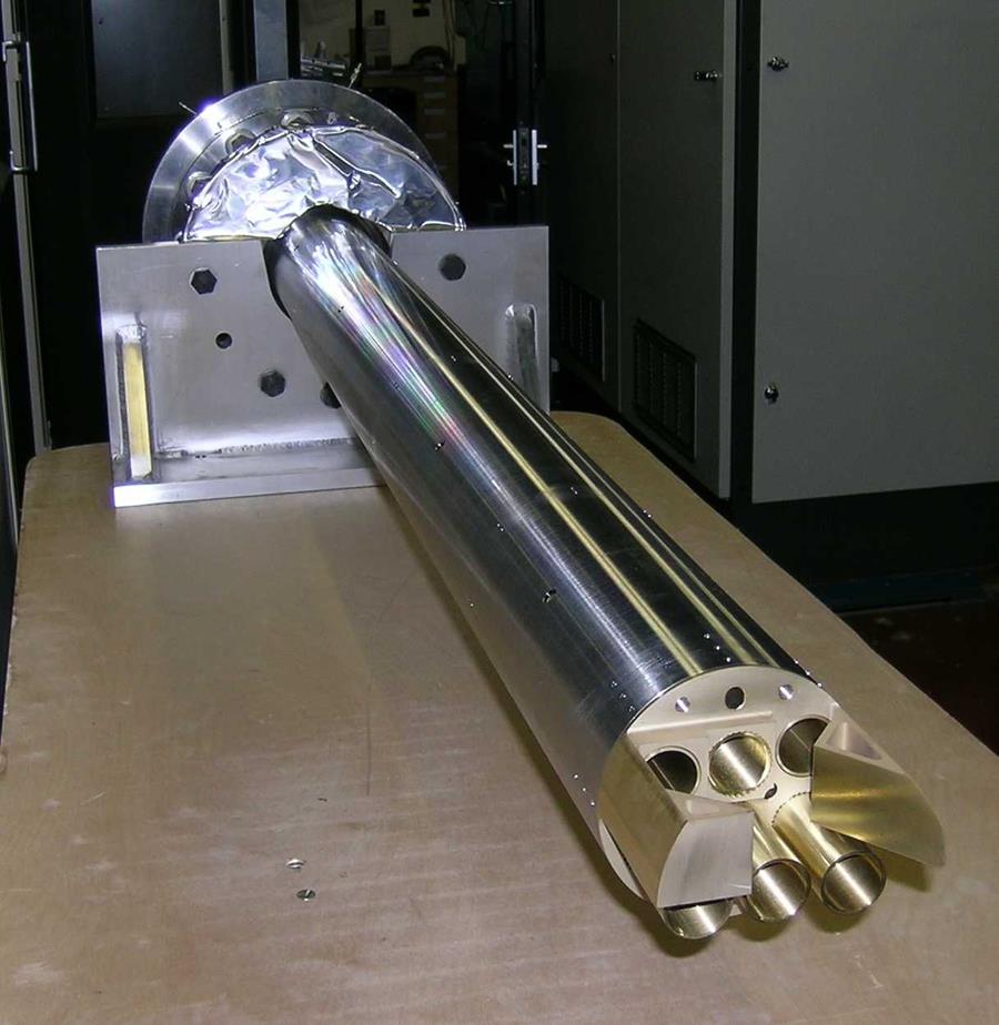
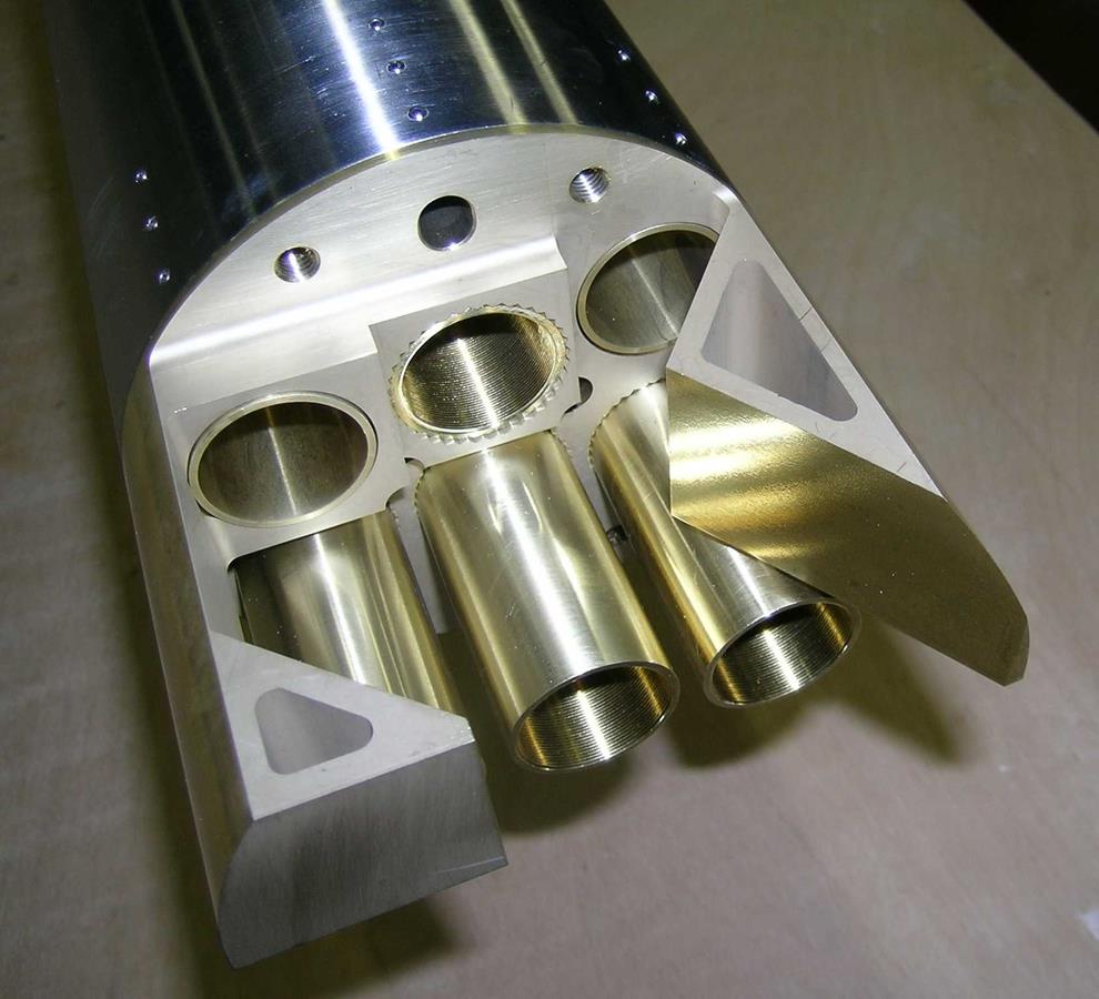
Here is a full view of the ECE mirror antenna, made from a single piece of Aluminium Bronze by turning, milling, spark and wire erosion.
Acknowedgements
Thanks to EDFA and its constituent laboratories – Luis Cupido, Alain Guigon, Elena de la Luna and Armin Scherber for awarding the contract to TK, to AEA Fusion – especially John Fessey and Trevor Edlington – for encouraging and guiding us though the many and varied problems we came across, to technical staff at JET for dealing with many of the interesting technical challenges – Valeria Riccardo, Tony Tiscornia, David Sands, Robert Pearce & David Starkey, to Simon Hanks at AEA Fusion's Special Techniques provided the double windows, to Nigel Boulding and has colleaues Ted, Neil and Nigel at Oxford Danyfsik in Oxford for the use of their clean room, to Paul Wiggins at AS Scientific for performing the welding we did not want to do and finally to the many people at TK were involved in the design and construction, which was designed by Stuart Froud and built by Trevor Walker.
